TUTORIAL NOTES:
This tutorial is intented as a companion to my ▶ YouTube Video, and its instructions apply ONLY to that specific hardware configuration! If you have not followed the video, please click above and do so -- otherwise these instructions may not work for your particular hardware setup!
No Warranties are Implied -- if you fry your Raspberry Pi, your Television or anything else, we are not responsible!
If you landed here without going through the other steps, please start here
Dismiss This Message
Configure HyperHDR
▶ NOTE: Many of the settings we are choosing are SPECIFICALLY to keep the CPU load down. This does two things:- Keeps the Raspberry Pi cool and consuming less power, and
- Keeps the latency as low as possible
If you are getting odd colors, be sure to scroll down to the Quirks section! But follow the next section first if you have not already set up your Capture device and LED hardware.
Pre-requisite!
Before we configure ANY of these settings, first set up your Television to the mode and settings you will use when watching TV. This way, what we configure from here on out can be (closely) matched to the way you normally watch TV.Video Capture
In the left pane, select Video Capturing: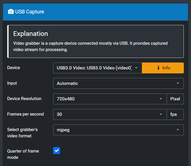
For Device, select your capture device -- usually it's the first option, and will say (video0). Leave Input on Automatic.
For Device Resolution, depending on your capture device, you can select various options. If possible, choose 720x480 or even 640x480 -- the aspect ratio does not matter here, and we're only looking for general color information so we do NOT need to look at an HD signal.
Using a lower resolution will require much less processing load on the Pi's CPU.
Choose 30 for Frames per Second.
These settings will NOT affect the frame rate or resolution of your Television signal.
This only affects what HyperHDR looks at for color information.
Select mjpeg for the grabber's video format.
Tick the box next to Quarter of frame mode -- this further reduces CPU usage.
TIP: If you later find that your LEDs appear to react before your Television picture, you might increase the Resolution and/or turn of Quarter of frame mode, to intentionally slow down the Raspberry Pi.
Some TVs do a lot of processing and show the picture at a slight delay that might lag behind the LEDs.
Set up LED Instance
Hopefully you counted how many LEDs are on each side of the TV, as well as the top. Click on LED Hardware in the left pane.▶ New Method (December 2025)
Due to the Raspberry Pi 5, I've added an alternate method that I recommend. This new SPI method will work on ALL supported Raspberry Pi boards:- Pi Zero 2 W (My Personal Recommendation)
- Pi 3 (including 3b & 3b+)
- Pi 4 & 4b
- Pi 5
Otherwise, if you've already connected the Green wire to GPIO 18 and are NOT using a Pi 5, simply follow the instructions below.
In my experience, if you are using a Pi Zero, 3 or 4 (not a 5) it seems to work better using the original GPIO 18 method. Using SPI I've experienced the occasional glitch, so unless you are using the Pi 5, I strongly recommend sticking with the GPIO 18 method I've always shown in my videos and tutorials.
Original Method using GPIO18At this point, you may see the FIRST LED on your strip light up; this is normal, and shows that we're on the right track!
Just please be aware that this method DOES NOT WORK on the Pi 5!
If you have connected the Green wire on a Pi 5 to GPIO 18, please relocate that wire as shown in the SPI instructions!
Click Here to go to the SPI instructions!
Assuming you have connected the Level Shifter green wire to GPIO 18 (sixth pin down on the right-hand side of the Pi header), as shown in the picture to the right, select the following:
For Controller Type, under RPi PWM, select ws281x. You may have to scroll up to find this option.
sk6812 Note: Choose the ws281x option even if you are using the sk6812 LEDs. Just be sure to select Use RGBW Protocol below, as the data format is slightly different.
You will get a stern warning from HyperHDR. IF you are using my One-Way Level Shifter, you can of course safely ignore this warning. My Level Shifter only presents about a 10kΩ impedance to that GPIO pin.
If you are using any other wiring method, you do so at your own risk to the sensitive GPIO pins of the Pi!
For most ws2812b & sk6812 strips, the RGB Byte Order is GRB, so start there.
For now, leave Refresh Time alone.
For Maximum LED Count, unless you have more than 256 LEDs you can just leave 256 there.
Make sure GPIO Number is set to 18
Leave the rest of the settings alone, but do select Use RGBW protocol if you have an RGBW strip such as the sk6812.
Now scroll down and click Save Settings.
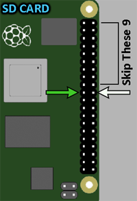 Assuming you have connected the Level Shifter green wire to the SPI0 MOSI pin
(tenth pin down on the
LEFT-hand side of the Pi header), as show in the picture to the right, select the following:
Assuming you have connected the Level Shifter green wire to the SPI0 MOSI pin
(tenth pin down on the
LEFT-hand side of the Pi header), as show in the picture to the right, select the following:
LED Layout
After the confirmation message disappears, scroll back up and click on LED Layout. If it's not already, expand Classic Layout (LED Frame). You should see something like this: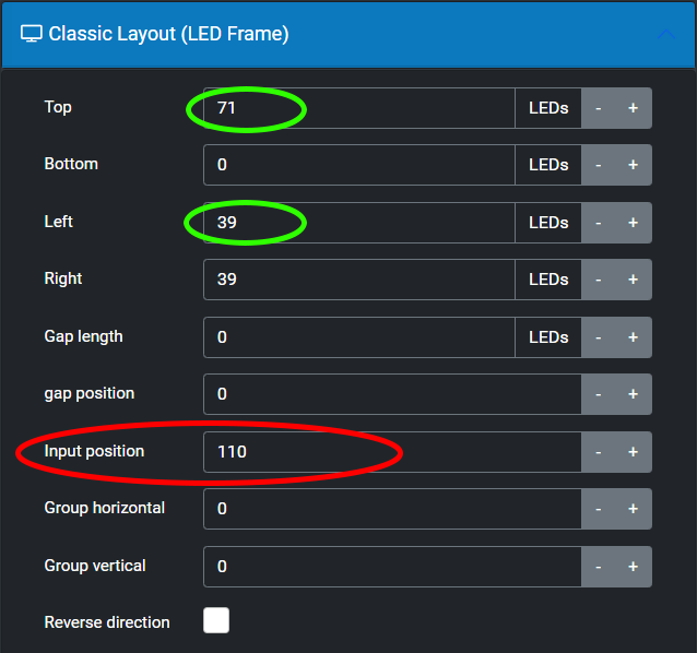
This is where you will enter the number of LEDs for the Top, Left and Right. Leave the Bottom, Gap Length and Gap Position all at zero.
HyperHDR assumes you start your LEDs at the upper-left corner, so you need to specify the ACTUAL start position. To do this, add up the TOP and one of the SIDEs (circled in green) to get your Input Position (circled in red), and enter that total.
▶ If you started your LED strip on the RIGHT side of the TV, click Reverse Direction above.
Now click Save Layout.
Advanced Settings
Next, expand Advanced Settings. I recommend using the numbers below as a good starting point: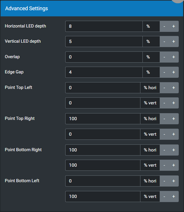
Once again, click Save Layout.
If done correctly, you should see something like this:
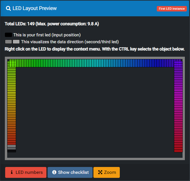
The BLACK pixel (rectangle) should be where you STARTING LED is; either the bottom-left or the bottom-right.
Quirks!!!
With certain capture devices, the default Hardware Picture settings are often very much wrong.To find the actual Minimum and Maximum values for each of these settings, we need to go back to the Terminal.
If you are using PuTTy, and it has logged you out, you will need to Right-Click in the Title Bar of the PuTTy window, and select Restart Session. This will prompt you to log in again.
Now type the following command in your SSH terminal:
v4l2-ctl -l
📋 COPY - then PASTE, then press ENTER
You might see something crazy like the following:
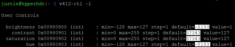
Those default values are the result of a bug in the Capture driver. Pay attention to the min and max values -- each of those items, brightness, contrast, saturation and hue, all have their own values depending on your capture device.
You will want to set each of these, within HyperHDR, to the middle of the range, except never set them to ZERO, as ZERO tells HyperHDR to use the Default, which will be that crazy number...
More sane recommended values, going by the above example, are as follows:
Be sure to set all of these settings (within HyperHDR) as above at least to start, but NEVER set any of them to 0 (zero).
Setting Min Max Value Brightness:-1281271Contrast:0255127Saturation:0255127Hue-1281271
Setting any of these values to ZERO tells HyperHDR to use the device default setting, which in most cases is very wrong. So making the Brightness and Hue 1 is just enough to override that default, without altering the actual value much.
Now later, if you find the LEDs are still lighting even on a dark or black screen, you may wish to reduce the hardware Brightness until that goes away.
If you manually set these settings using v4l2-ctl, they will reset every time you restart the Pi! So use HyperHDR to configure these settings!
The above recommendations basically sets everything in the middle of the range; from there we can further customize it in software, in the next step.
We will set up the Automatic Signal Detection a bit later, so for now just scroll down and click Save Settings.
You should see your strip fully lit based on whatever is on the screen at this point.
You might have to pull up something bright on your Source device to get all of the LEDs to light.
▶ Next: Color Calibration
◀ Prev: Configure the Software
↩ Back to the Beginning

